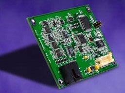
5000RSU Serial Controller (Discontinued May 2007)
Merkmale
-
Technische
Artikelnummer(n)
618614-000
Technologie
AccuTouch® 5-Draht-Widerstandssensorik
Abmessungen
2.1" x 3.30" x 0.40" / 53.3 mm x 83.82 mm x 10.16 mm
Schnittstelle
EIA 232E (Serial RS-232), DCE configuration. 8 Data Bits, 1 Stop Bit, No Parity, Full Duplex.
DSR is pulled HIGH (>+3V) by the 5000RSU when connected and powered. DTR can be asserted to interrupt the flow of data from controller.Auflösung
4096x4096, size independent
Conversion Time
Approximately 15 ms per coordinate set.
Stromversorgung
+5 VDC, nominal (+4.75 to +5.25 VDC) or +12 VDC, nominal (10.8V to 13.2V)
NOTE: Power may be supplied as either 5V or 12V, but not both.Eingangsspannung
+4.75 to +5.25 VDC
Baudrate
9600 (default) and 19200
Reliability
Prediction Method: MIL-HDBK-217-F2 (Ground benign)
25°C: 386,921 hours
35°C: 283,022 hours
Prediction Method: Bellcore
25°C: 924,034 hours
35°C: 591,432 hoursConstruction
Four-layer surface-mount design with internal ground plane for EMI suppression
Flammability
The printed circuit board substrate is rated 94V0. All plastic components, such as headers and connectors, are also rated 94V0
Shock and Vibration
The controllers, when packaged in Elo standard controller shipping container, shall meet the requirements of the National Safe Transit Association project 1A test procedure
ESD
Controller Alone
- Per EN 6100-4-2 1995. Level 4.
- Contact Discharge - 8kV.
- Air Discharge - 15kV positive and negative polarity.
These ESD impulses are applied directly to the pins on P2.
The Serial port is tested to simulate ESD impulses applied to the monitor connectors. This is done by applying the ESD impulses to P1 via a 560 ohm resistor and a 10" wire.
Controller and Screen
When ESD impulses are applied to an Elo surface capacitive screen connected to the 5000RSU controller, the screen and controller combination is tested to the standards shown below:
- Nevada State Reg No. 14, electrostatic discharge (ESD) Part 5.1.1 and 5.1.2. (no disturbance to 20 kV and self-recover from disturbance up to 28 kV). Tested with positive and negative polarity.
- Nevada State requirement for AC 40 kV/500 MHz.LED Diagnostic Characteristics
The CTR-500000-SC-RSU-00 controller has one LED status indicator - D10.
The D10 LED indicates the controller's status. At power on, the LED is not lit. During the microprocessor's diagnostic self tests, the LED is lit continuously. Upon completion of self tests, the LED blinks at a rate of once per second. Thereafter, when a touch is detected, the LED lights continuously. When no touch is detected, the controller LED resumes blinking at a rate of once per second. If an error condition is detected, the LED blinks at a rate of twice per second.Jumpers
The jumpers on the CTR-500000-SC-RSU-00 controller are enabled by placing shorting jumpers on specific jumper headers as shown in Table 6 or disabled by leaving the locations open.
Jumper Function when jumper is present
J1 Allow FLASH memory reprogramming
J2 Reinitialize NVRAM on power upAktuell – Betriebsmodus
80 mA, maximum at +5 VDC. Typical power dissipation is 0.325W at 5V, 0.780W at 12V.
Inrush current of up to 600mA for 50mS following power on.
Supply must be capable of sourcing 200 mA, minimum.Betriebstemperatur
0°C to 65°C
Betriebsumgebung
Full Surface Capacitive SmartSet protocol
Customer specific protocol
Initial/ Stream/ Untouch ModesLagertemperatur
-25°C to 85°C
Feuchtigkeit
Operating: 10% to 90% RH, noncondensing
Storage: 10% to 90% RH, noncondensingHöhe
10,000 feet
MTBF
50.000 Stunden, nachgewiesen
Zertifizierungen und Konformitätserklärungen
Elo controllers are "CNR/USR" UL Recognized Components for USA and Canada, Category NWGQ2, Information Technology Equipment Including Business Equipment.
Elo controllers are TUV Bauart certified as components.
Elo controllers have been tested for compliance with FCC Part 15 Class B limits.
Depending on the application, it may be necessary to pay special attention to system grounding and shielding, and it may be necessary to apply ferrite suppressor beads.
RoHS Declaration of ComplianceMontageoptionen
All mounting holes are plated through for chassis ground connection
Connectors and Pin Definitions
All connectors are located along one side of the controller. Connector descriptions and pin-outs are described in the following sections.
Power/Interface Connector - a MOLEX 53505-2090, 1.25mm pitch 20 pin, top contact style connector, intended to be used with single wired pins in a 20 pin header. Matching header is MOLEX 51127 housing, with MOLEX 50516 terminals. For more information please see the Molex website.
The controller supports hardware handshaking. If the handshaking signals are not connected, the controller defaults to a transmit enabled mode. If the handshaking signals are connected, then the controller will stop transmitting when either DTR or RTS is asserted (driven to logic "1") by the host. When the controller's receive buffer is full, it asserts (drives to logic "1") the CTS signal to halt the host.
Touchscreen Connector - an AMP 103635-4 or 103906-4.Weitere Merkmale
Serial cable (P/N D16890-000)
Optional Software/Hardware Handshaking
RTS/CTS
